Automated Drone Flight: Distance to Objects
- H-Barrio

- Sep 3, 2021
- 5 min read
Updated: Sep 6, 2021
In our previous TELLO drone automated flight, we tried to complete a circle around an object of interest. Coupled control dynamics and minor external disturbances make keeping a constant distance to an object difficult in a preprogrammed flight schedule. A minor rotor imbalance will cause a large error in the ratio of lateral movement to rotation speed, forcing the flight path out of a circle. To solve this problem, we will try to keep a fixed distance to our object of interest. To achieve this fixed distance keeping, we will first obtain the distance to an object that is highly discernible without machine learning vision. The object has a known size and a telltale shape.
For highly-discernible, know-size objects look no further than ArUco markers. This type of fiduciary marker was developed at the University of Cordoba for augmented reality applications. You can obtain ArUco markers from this site. For example, we are using the 4x4 marker with identification number 0, which looks like this:

The camera in our drone should easily distinguish the contrasting black and white pattern and read its content. In addition, the size of our printed marker is a known 50mm on its side, so that we will be able to determine the distance to it with its apparent in-image size.
The videos we are using are these:
They are all like this one:
TELLO EDU box "mission pads" are 20cm long, so 2 pads are approximately 40cm to the wall with the ArUco marker. We will try to determine this distance from the apparent shape of the marker.
Before we start, you may need to alter the installation of OpenCV to work with the ArUco utilities. You may, in most systems, do the following to remove the current OpenCV installation and replace it with the "contrib" installation:
# For ARuCO
!pip3 uninstall opencv-python -y
!pip3 install opencv-contrib-python==4.5.3.56
At the time of writing, 4.5.3.56 is the latest version that prevents certain errors in the rectangle drawing tool from happening. Therefore, we need the following modules:
import cv2
import numpy as np
from matplotlib import pyplot as plt
Our marker images are in video format. Therefore, we will have to define a function to grab a frame from these videos. All frames show the marker for these example videos. We grab a frame from a given second of the recording with this function:
def getFrame(sec, video):
    vidcap = video
    # Cue to relevant time:
    vidcap.set(cv2.CAP_PROP_POS_MSEC, sec*1000)
    success, img = vidcap.read()
    vidcap.release()
    return img
We can set the relevant frames into a list using this code, just grabbing the middle frame of the video:
videos = ['20cm.mp4', '40cm.mp4', '60cm.mp4']

dist_frames = []

for video in videos:
    vidcap = cv2.VideoCapture(video)
    fps = vidcap.get(cv2.CAP_PROP_FPS)
    frame_count = vidcap.get(cv2.CAP_PROP_FRAME_COUNT)
    duration = frame_count/fps
    s_to_cap = int(duration/2)
    one_frame = getFrame(s_to_cap, vidcap)
    dist_frames.append(one_frame)
If we plot the frames, we will see the frame and the marker in it:
for f in dist_frames:
    plt.imshow(f)
    plt.show()

The frames so the height reading that we inserted into our own video feed in this other post. The images correspond to 20cm distance, 40cm, and 60cm.
We can access the built-in OpenCV marker dictionary and proceed to detect them in our images:
arucoDict = cv2.aruco.Dictionary_get(cv2.aruco.DICT_4X4_50)
arucoParams = cv2.aruco.DetectorParameters_create()
corners = []
for f in dist_frames:
    c, _, _ = cv2.aruco.detectMarkers(f, arucoDict, parameters=arucoParams)
    corners.append(c)
The detection function returns the corners of all detected markers, their identification number, and the image points that are candidates for being a marker and are rejected. We send these last two pieces of information to the oblivion variable "_". The corners variable contains the single detected marker for each of the images:
[[array([[[354.,  44.], [568.,  41.], [566., 257.], [359., 258.]]], dtype=float32)],
[array([[[353., 103.],[465., 102.],[466., 216.],[356., 217.]]], dtype=float32)],
[array([[[455., 123.], [530., 123.], [529., 199.], [455., 199.]]], dtype=float32)]]
These detected marker corners can be plotted on top of the original video frame to ensure that we are indeed detecting the markers. Next, we will draw a rectangle (a bounding box, if you will) for each of the frames and a circle in the center of the marker:
def show_markers(frames, corners):
    f_c = zip(frames, corners)
    for f, c in f_c:
        img = f.copy()
        coords = np.int0(c).reshape((4, -1))
        topLeft = coords[0]
        bottomRight = coords[2]

        # draw the bounding box of the ArUCo detection
        red_color = (255,0,0)
        cv2.rectangle(img, topLeft, bottomRight, red_color, 3)
        # compute and draw the center of the ArUco

        cX = int((topLeft[0] + bottomRight[0]) / 2.0)
        cY = int((topLeft[1] + bottomRight[1]) / 2.0)
        cv2.circle(img, (cX, cY), 10, red_color, -1)

        # show the output images
        plt.imshow(img)
        plt.show()
The function replicates the frames with the bounding box tightly fitting the detected marker:
show_markers(dist_frames, corners)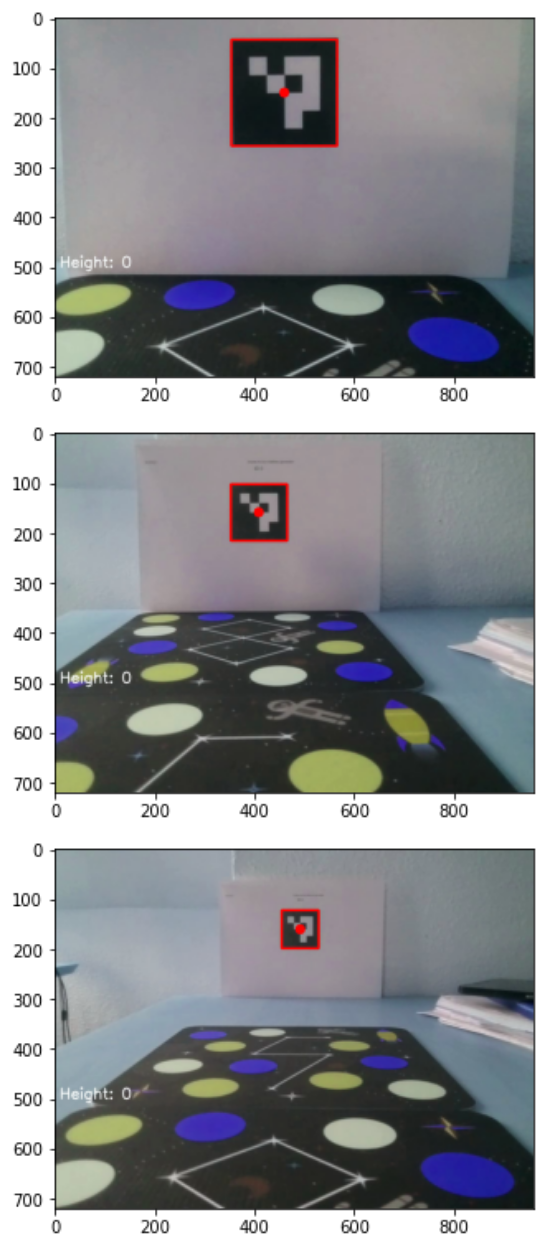
Now that the marker is detected, we have its apparent form. This gives us directly the distance from the camera sensor plane to the marker plane. Image recording sensors insert a distortion into the recorded image. It may be minor for normal cameras or huge for fisheye and 360º cameras. In our case, the camera matrix parameters and distortion values are taken from this forum post are:
camera_matrix = np.array([[921.170702, 0.000000, 459.904354],
                          [0.000000, 919.018377, 351.238301],
                          [0.000000, 0.000000, 1.000000]])

dist = np.array([-0.033458,
                 0.105152,
                 0.001256,
                 -0.006647,
                 0.000000])
Using the camera matrix intrinsic parameters and the distortion, we can define this function that will return the distance, in meters, from the camera sensor to the marker:
def find_distance(c, m_size=50, cm=camera_matrix, d=dist):
    c = np.array(c)
    pose = cv2.aruco.estimatePoseSingleMarkers(c.reshape(-1,4,2),
                                               50, cm, d)
    translation = pose[1]
    distance = np.linalg.norm(translation)

    # in SI units, meters:
    return distance/1000
The pose estimation function returns the rotation vectors, and the translation vectors for the detected markers, the distance to the marker is then the norm of the translation vector. We can check these distance results. We know them to be 20, 40, and 60cm:
for c in corners:
    d = find_distance(c)
    print(d)
0.2226871252502698
0.41994376863351207
0.62753284208754Good, there is a minor error due to the marker's location in a crumbled piece of paper and the location of the lens in the drone. However, the values are at least very believable to their second decimal place. With this distance calculation, we can now upgrade our marker detector to show an overlay text with the distance to the marker on top of our recorded frame:
def show_markers(frames, corners):
    f_c = zip(frames, corners)
    for f, c in f_c:
        img = f.copy()
        coords = np.int0(c).reshape((4, -1))
        topLeft = coords[0]
        bottomRight = coords[2]

        # draw the bounding box of the ArUCo detection
        red_color = (255,0,0)
        blue_color = (255, 0, 0)

        cv2.rectangle(img, topLeft,bottomRight, red_color, 3)
        # compute and draw the center of the ArUco marker
        cX = int((topLeft[0] + bottomRight[0]) / 2.0)
        cY = int((topLeft[1] + bottomRight[1]) / 2.0)
        cv2.circle(img, (cX, cY), 10, red_color, -1)

        d = find_distance(c)
        font = cv2.FONT_HERSHEY_SIMPLEX
        org = (10, 550)
        fontScale = 1

        thickness = 2
        d_txt = f'Distance: {d:.2f}m'

        image = cv2.putText(img, d_txt, org, font,
                           fontScale, blue_color, thickness, cv2.LINE_AA)

        # show the output images
        plt.imshow(img)
        plt.show()
The markers, with bounding box and distance, look like this:

Now we have a reliable method to extract distance from images. Furthermore, we can translate this method to a real-time video feed and obtain a continuous distance-to-target reading to allow our drone to keep its station or complete a real circle around a marker object.
Do not hesitate to contact us if you require quantitative model development, deployment, verification, or validation. We will also be glad to help you with your machine learning or artificial intelligence challenges when applied to asset management, automation, or intelligence gathering from satellite, drone, or fixed-point imagery.
The Google Colab notebook with this post is here.


Comments